
The System
One cable. Hundreds of measuring sections. Two readings at every one.
The IHTC Thermal Monitoring System is a sensing cable with integrated sensing modules evenly distributed, built to make continuous temperature part of how you run your facility.

Sensing
Three heat paths, one integrated system, no blind spots.
A failing asset generates heat, which travels by radiation, conduction and convection; a single-mode detector senses one of them. IHTC reads all three. An infrared element measures the radiated temperature of the surface it faces, from a distance, so a heat source registers before its heat has warmed the air. The sensing cable itself measures its surroundings by conduction and convection. Side by side, the two readings tell a rise on the asset from a rise in the room.
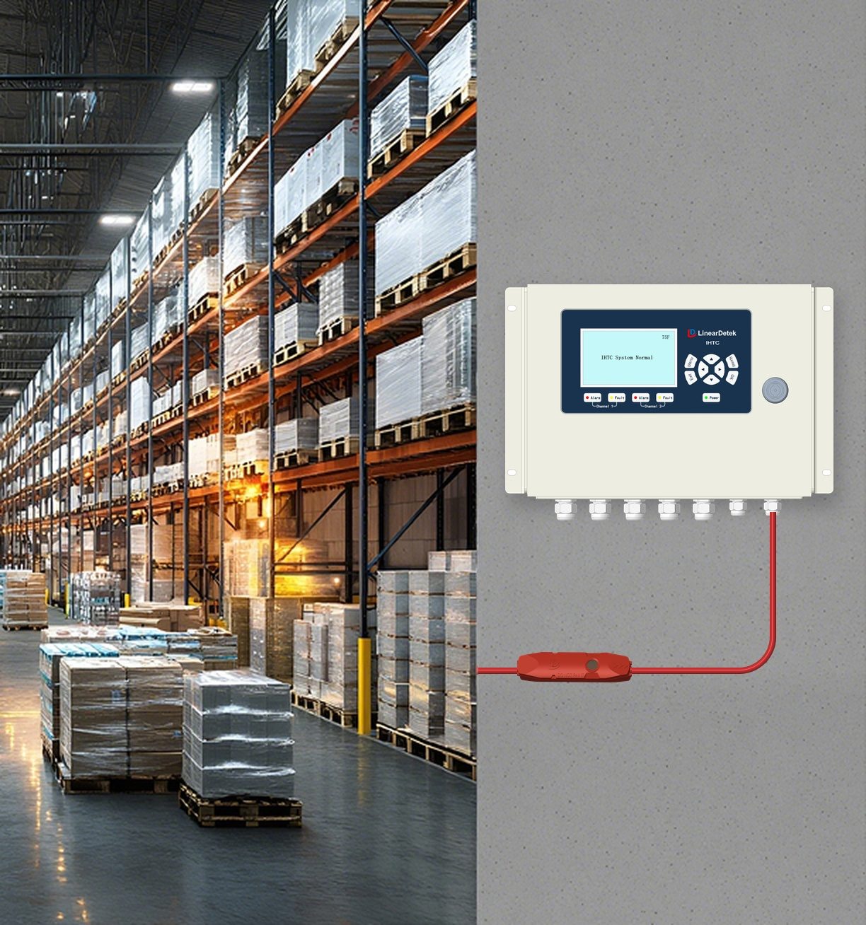
Everything is integrated into one sensing cable that threads through enclosed racks, stacked trays and raised floors, so there is no optical path to keep clear and no per-point wiring or radio link to bring out. The whole route is instrumented. What hides a surface from a thermal camera does not hide it from IHTC.
Deployment
How it works
- Route the cable along the assets to protect — racks, belt lines, trays, busways.
- Connect the control unit. One control unit supports up to 6,560 ft (2,000 m) and 400 sensing sections.
- Stream the data. Per-section temperatures, status, and event history over RS485 Modbus RTU into your SCADA, BMS, or DCIM — or into IHTC Monitor. Per-channel dry contacts can interlock your own equipment controls.
- Act on location. Alerts name the section, within 16 ft (5 m). Heat events are responded to as scheduled maintenance instead of incidents.
Software
IHTC Monitor software.
A desktop application: live dashboards, trend charts, data logging, alarm and fault event history, and support for up to 32 full IHTC systems on one bus. It runs on your own network — or choose the Monitored Service for cloud-hosted dashboards.
Two ways to deploy.
| Path | What you get | Best for |
|---|---|---|
| Integrate yourself | Hardware plus the documented Modbus register map (IHTC-COM-001). Your team connects IHTC to your SCADA, PLC, BMS, or DCIM. | Operations with existing monitoring platforms and integration staff. |
| Monitored Service Coming soon | Hosted dashboards, alert notifications, IHTC Monitor, and an annual thermal report, as an annual subscription. Contact us for availability. | Sites without a SCADA or BMS. |
Specifications
System at a glance
| Coverage | Up to 6,560 ft (2,000 m) per control unit; 2 channels × 3,280 ft (1,000 m) |
|---|---|
| Sensing sections | Up to 400 sections per control unit (200 per channel) |
| Location accuracy | 16 ft (5 m) |
| Monitoring modes | Fixed temperature 185 °F (85 °C) and rate-of-rise, selectable sensitivity |
| Restorability | Self-restoring after exposure up to 248 °F (120 °C) |
| Operating ambient | −22 °F to 131 °F (−30 °C to 55 °C) |
| Communications | RS485 Modbus RTU; per-channel dry-contact outputs |
| Power | 24 VDC nominal (20.4–26.4 VDC) |
| Ingress rating | IP67 — sensing cable (manufacturer rating) |
Prove it in 60–90 days.
The Evaluation Kit is a fixed-fee pilot on one application: hardware, commissioning, tuned alert thresholds, temporary monitoring for the pilot period, and an insurer-ready thermal report. The full fee credits toward a deployment, and you keep your data.